


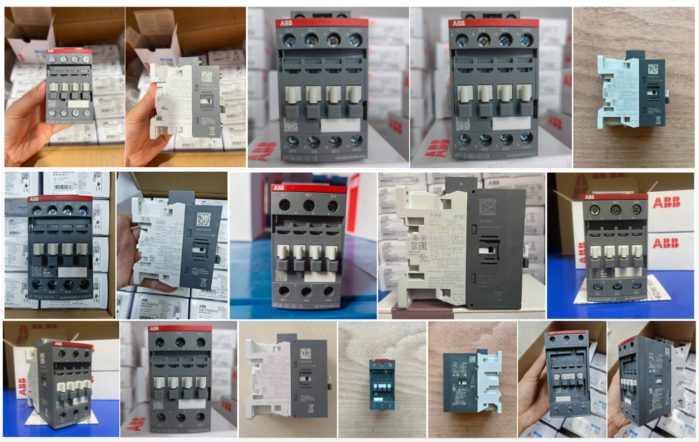
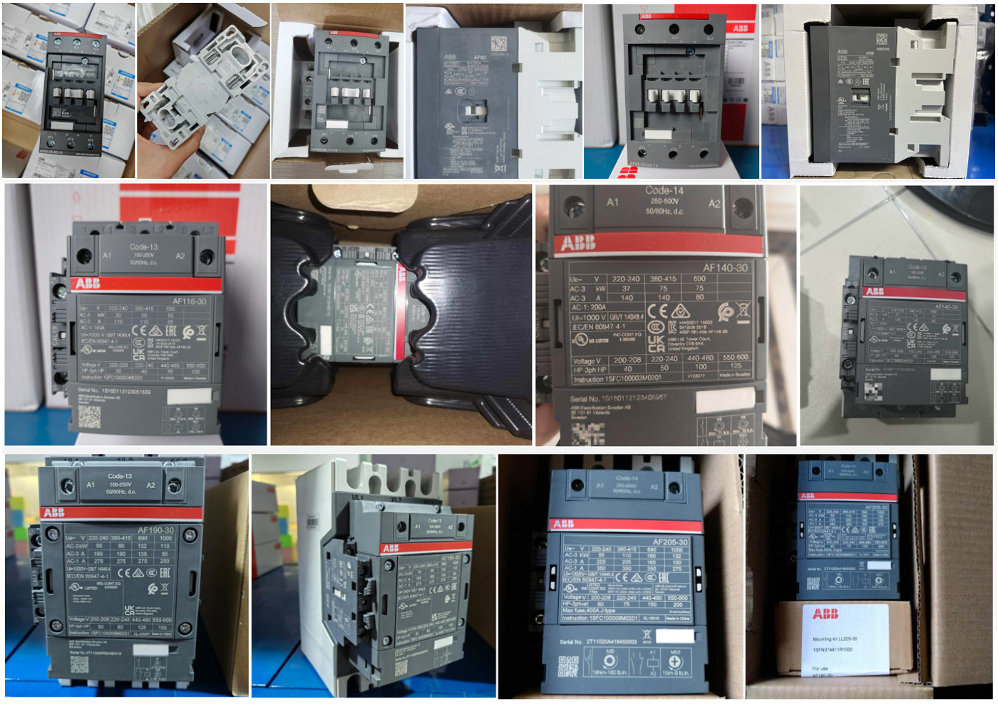
A list of core parameters for ABB AF series contactors:
The table below summarizes the key electrical parameters of the main models in the AF series, from AF09 to AF1250. A "√" indicates that the characteristic is applicable across the entire series.
| Model | AC-3 Power (400V) | AC-1 Current (690V) < 40°C | Coil voltage range (typical) | Auxiliary contact configuration | Built-in surge suppressor | Mirrored contacts | |||||
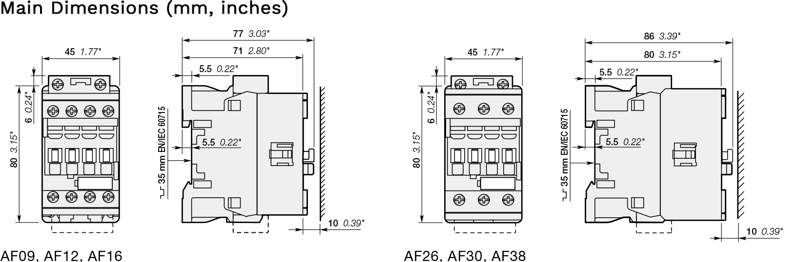
| AF09 | 4 kW | 25 A | 24...500V AC / 20...500V DC | Optional | √ | √ | |||||
| AF12 | 5.5 kW | 28 A | Same as above | Optional | √ | √ | |||||
| AF16 | 7.5 kW | 30 A | Same as above | Optional | √ | √ | |||||
| AF26 | 11 kW | 45 A | Same as above | Optional | √ | √ | |||||
| AF30 | 15 kW | 50 A | Same as above | Optional | √ | √ | |||||
| AF38 | 18.5 kW | 50 A | Same as above | Optional | √ | √ | |||||
| AF40 | —— | 40 A | 24...500V AC / 20...500V DC | Optional | √ | √ | |||||
| AF52 | —— | 52 A | Same as above | Optional | √ | √ | |||||
| AF65 | —— | 65 A | Same as above | Optional | √ | √ | |||||
| AF80 | —— | 80 A | Same as above | Optional | √ | √ | |||||
| AF96 | —— | 96 A | Same as above | Optional | √ | √ | |||||
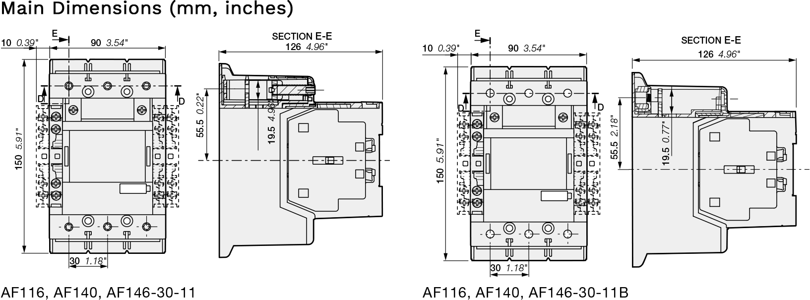
| AF116 | 55 kW | 96 A | Same as above | 1NO+1NC | √ | √ (Available) | |||||
| AF140 | 75 kW | 140 A | Same as above | Optional | √ | √ (Available) | |||||
| AF190 | —— | 190 A | Same as above | Optional | √ | √ (Available) | |||||
| AF205 | 110 kW | 205 A | Same as above | Optional | √ | √ (Available) | |||||
| AF265 | 132 kW | 265 A | Same as above | Optional | √ | √ (Available) | |||||
| AF305 | —— | 305 A | Same as above | Optional | √ | √ (Available) | |||||
| AF370 | 200 kW | 370 A | Same as above | Optional | √ | √ (Available) | |||||
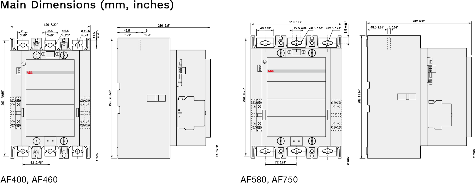
| AF400 | 200 kW | 400 A | 100...250V AC/DC, etc. | Optional | √ | Optional | |||||
| AF460 | 250 kW | 460 A | Same as above | Optional | √ | Optional | |||||
| AF580 | 315 kW | 580 A | Same as above | Optional | √ | Optional | |||||
| AF750 | 400 kW | 750 A | Same as above | Optional | √ | Optional | |||||
| AF1250 | —— | 1260 A | Same as above | Optional | √ | Optional | |||||
Key Features Explained
As can be seen from the parameters above, the AF series has the following significant characteristics:
● Wide Voltage, AC/DC Universal Coil: This is the core advantage of the AF series. A single contactor can cover a wide voltage range (e.g., 100-250V AC/DC), suitable for different global power grid standards. There is no need to replace the coil for different control voltages, significantly simplifying selection and inventory management.
● Strong Resistance to Voltage Fluctuations: The electronic coil can withstand short-term voltage drops and interruptions, ensuring continuous operation of the equipment when the power grid is unstable. It complies with SEMI F47 standards and is particularly suitable for applications with strict power quality requirements.
● Integrated Surge Suppressor: A surge suppressor is integrated inside the coil, eliminating the need for additional purchase and installation, simplifying design and saving cabinet space.
● "Mirror Image Contacts" and Safety: Some models have built-in NC auxiliary contacts that are "mirror image contacts," compliant with IEC 60947-4-1 standards. This provides enhanced safety diagnostic capabilities, especially suitable for safety circuits requiring high reliability. Large 4-pole contactors can also be equipped with auxiliary contact blocks featuring mirror image contacts.
● Strong Wiring Capabilities: The main circuit wiring capabilities vary significantly between different models, ranging from small-gauge AWG 16-10 wires to large-gauge cables capable of connecting up to 4/0 AWG (approximately 120mm²) and even 500 MCM (approximately 240mm²), meeting the diverse needs of everything from small-power motors to large-scale power distribution systems.
Key Features Explained:
ABB contactor model naming contains crucial information; understanding this can help you quickly identify the product you need. For example, consider model AF50-30-11-13:
● AF50: Series and frame current (50A).
● 30: Indicates 3-pole (3 Pole) normally open main contacts.
● 11: Indicates auxiliary contacts are 1 normally open (1NO) + 1 normally closed (1NC).
● 13: Coil voltage code, corresponding to 100...250V AC/DC.
● Note: The correspondence between the coil voltage code and the voltage range is crucial for model selection. For example, code -11 typically corresponds to 24...60V AC / 20...60V DC, while -13 corresponds to 100...250V AC/DC, and -14 corresponds to 250...500V AC/DC.


| Size |